04 Feb

How to Change Your Morgan’s Oil (NAPA – 2 February 2019)
[Changing your vehicle’s engine oil is not difficult but unfortunately we sometimes fail to perform this recurring task. This can happen for any number of reasons; lack of time, lack of space, lack of tools, etc. However, changing the oil is one of the most important things you can do to keep your Morgan on the road. If you can’t do it at home take the car to a oil changing service in town. They are everywhere. Just don’t forget to get it done. It is best to change your oil as suggested by your Morgan handbook, but in general every 3,000 – 5,000 miles or three months or so. Changing the engine oil too often won’t hurt the car! In addition to mileage you may need to change the engine’s oil for other reasons. In many of the places we live the temperature and humidity changes wreak havoc on our engine’s oil. Water from condensation will contaminate the engine’ oil and dilute it’s ability to lubricate your motor. You may also want to change the engine’s oil when your prepare you car for a long period of disuse, e.g. the winter. (Oil can turn acidic over time and that’s not good.) Mark]

Things you’ll need from your garage :

  • Oil catch/recycle container
  • Funnel
  • New oil filter
  • Oil drain plug gasket (Using a new one is recommended)
  • 4-5 qt. new oil*
  • Oil filter wrench set**
  • Clean rags
  • Car jack
  • Jack stands
  • Safety glasses
  • Mechanics work gloves
  • Hand cleaner

*Check your owner’s handbook for your vehicle’s oil capacity.

**If you plan to change your oil regularly, consider investing in a small tool set, an oil filter wrench set, a quality floor jack and jack stands.

Step 1 – Park your car on a level surface and apply parking brake.

Run your engine for 5 minutes before draining oil, as warm oil drains faster than cold. Do NOT drain oil that is at full operating temperature as it will be too hot to safely handle.  It is recommended that you remove the key for the ignition to preclude any accidental engine starts.

Step 2 – Jack your car up and place it on jack stands.

A jack alone will not safely support the full weight of your car. Consult your manual for the proper jacking points. The placement of a jack stand is just as important as the jack placement. The wrong placement can damage your car’s suspension or body parts.

Step 3 – Locate the oil drain plug and place the drain pan below.

The oil drain plug is usually near the front center of the engine, but some vehicles have more than one plug. Check your manual for the exact location. Loosen the plug with a socket or wrench. Make sure that the drain pan is large enough to hold 4-5 quarts of oil or more.

Step 4 – Unscrew the plug by hand.

Remove the plug by hand. While unscrewing the plug, push it back towards the vehicle. This keeps oil from rushing out until you are ready to remove the plug from the hole.  Note: For engines with oil drains on the side, the oil is likely to drain at an angle, e.g. squirt out a foot or so.   Position the drain pan to catch it and be sure to adjust the pan’s location as it drains. 

[I have had lots of oil squirt onto the floor, outside to the pan, by not paying attention. Mark]

Step 5 – Drain all oil.

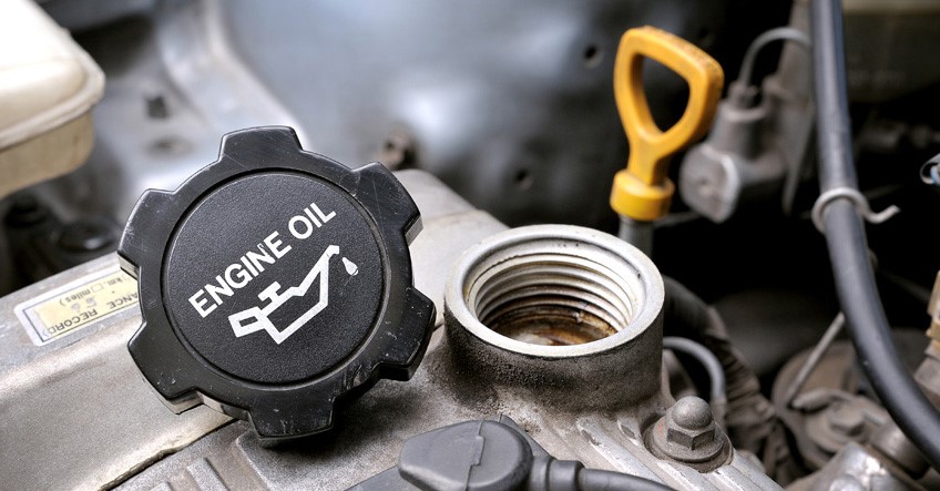
To speed up the draining process, remove the filler cap located on the top of the engine and allow air to enter from the top.

Step 6 – Replace oil plug.

Tighten the oil plug by hand and ensure it is not cross-threaded. Once the plug is snug, finish tightening it with a wrench or by hand. Always use a new drain plug gasket if you have one and never over-tighten the drain plug.

Step 7 – Remove existing oil filter.

Place the oil pan underneath the old filter to catch any remaining oil while unscrewing it. Remove the old filter using an oil filter wrench if you have one.  [Sometimes a strap wrench can be used, or if necessary, stick a screw driver into the body of the filter to give you something to turn. Use a rag to clean the mounting surface. Make sure that the sealing O-ring from the old filter is not stuck to the mounting surface on the engine.

Step 8 – Lubricate new filter and screw into place by hand.

Lightly coat the rubber seal of the new filter with fresh oil. It’s usually not necessary to tighten the oil filter with the wrench. Refer to the filter’s instructions. Once the filter is installed, lower the car.

Step 9 – Clean the oil filter neck and pour in the new oil using a funnel.

Typically, you will use 4 to 5 quarts of oil, but check your manual for your vehicle’s oil capacity. Fill to three-quarters of the engine’s capacity to avoid overfilling, as there is always oil that does not drain. Then replace the cap.

Step 10 – Run the engine for a few minutes to make sure there are no leaks.

Check the area around the oil drain plug and the filter for any leaks. If you notice a leak, shut the engine off immediately and remedy any leaks. Check the dipstick afterward and add more oil if necessary.

Step 11 – Dispose of the used oil properly.

Bring your used oil to a recycling center to recycle the oil for you (or many auto parts stores or oil change service business will take it but check with them first).  These are the only acceptable methods for oil disposal.

IMPORTANT TIPS:

  • Make sure your car is securely supported.
  • Record the date and mileage after you change the oil so you will know when your car is due for another oil change.  
  • Handle hot motor oil with extreme caution.
  • Use mechanic’s gloves to keep your hands protected and clean.
  • Only dispose of used motor oil and filters at authorized locations.
 
25 Nov

Drill Bits Buying Guide (www.lowes.com Nov 2018)

Learn about the different types of drill bits so you can choose the right ones for your project and for the material you’re drilling.

Types of Drill Bits: Materials and Finishes

The materials from which bits are manufactured and the finishes applied to them play a significant role in the life and performance of the bit. Common materials and finishes:

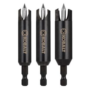
  • High-Speed Steel (HSS) drill bits can drill wood, fiberglass, PVC (polyvinyl chloride) and soft metals such as aluminum.
  • Cobalt drill bits are extremely hard and dissipate heat quickly. They’re mostly used for boring in aluminum and tough metals such as stainless steel.
  • Black oxide-coated HSS drill bits have a finish designed to help resist corrosion and increase durability. They last longer than basic HSS bits and work well on a variety of materials, including metal, hardwood, softwood, PVC and fiberglass.
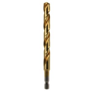
  • Titanium-coated HSS drill bits produce less friction. They’re tougher than basic HSS bits and stay sharp longer. They work for drilling wood, metal, fiberglass and PVC.
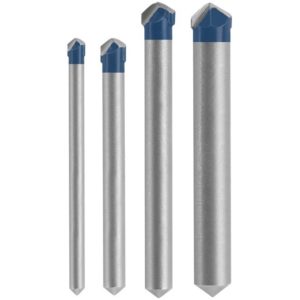
  • Carbide-tipped drill bitsstay sharp much longer than steel, HSS or titanium bits. They’re effective for drilling tile and masonry.

Drill Bit Construction

For a typical drill bit, the angle of the point helps determine what type of material the bit can drill. Flatter points — such as those with 135-degree angles — are suited for drilling into harder material. They may require a pilot hole to keep the bit from wandering. Bits with steeper points — such as those with 118-degree angles — are suited for softer material. They stay on center better and produce cleaner entry and exit holes. Bits with split-point tips improve drilling accuracy by keeping the bit from wandering when you begin to drill.

Bit size reflects the diameter of the body. Some projects call for specific drill bit sizes, but a bit set that includes sizes from 1/16-inch to 1/4-inch will handle many jobs around the home and workshop. You can add larger bits – 5/16-inch, 3/8-inch, 7/16-inch and 1/2-inch bits if you need them.

The chuck on a hand drill or drill press secures a drill bit to the tool along the bit’s shank. A smaller drill for work around the house typically has a 3/8-inch chuck. More powerful drills for heavier applications have a larger, 1/2-inch chuck. Drill presses also have larger chucks — 1/2-inch or 5/8-inch, for example. The bit shank size must not exceed the chuck size of the drill. A larger bit may have a reduced shank — a shank with a smaller diameter than the body of the bit — allowing you to use it with smaller chucks.

  • A round shank allows you accurately center a bit in the chuck.
  • A hex shank has flat surfaces, allowing the tool to grip the bit more securely for greater torque. Hex shanks such as the one in the image above work with quick-change chucks — common on cordless drills — allowing you to insert and remove them without tightening and loosening the chuck.
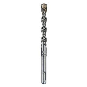
  • An SDS (slotted drive system) shank is designed for use on a hammer drill; it fits a spring-loaded chuck that doesn’t require tightening. The bit can move forward and backward with the hammering motion of the drill while flattened areas and slots on the shank allow the chuck to hold the bit.

Twist Drill Bit – A twist bit is the most common type of drill bit for home use. It works for general-purpose drilling in wood, plastic and light metal.


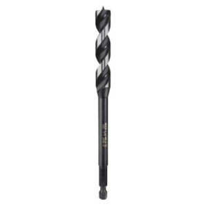
Brad-Point Drill Bit – A brad-point bit is designed for boring into wood. The brad at the center of the bit tip helps position the bit precisely for accurate drilling and produces a clean exit point in the work piece. The flutes — grooves that wrap around the bit and channel away chips and dust — are extra-wide to remove more material.Auger Drill Bit – An auger bit, another type of wood-boring bit, has a screw tip that starts the hole and pulls the bit through the work piece. These bits can be as long as 18 inches. As with the brad-point bit, large flutes help remove chips and dust.  An auger bit with a hollow center provides even more chip removal, one with a solid center is stronger and more rigid.Self-Feed Drill Bit – A self-feed bit bores through wood. Like the auger bit, a screw at the tip helps position the bit and draws it through the work piece. However, this bit is more compact. It doesn’t have the standard flutes of a twist bit, so you need to pull the bit back periodically to clear away chips and dust.
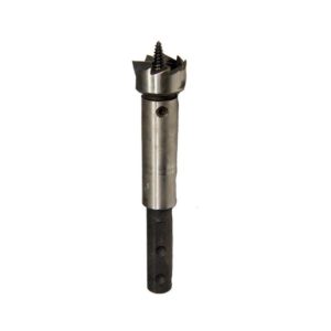
Installer Drill Bit – An installer bit is a specialized twist bit designed for installing wiring. The bit can be up to 18 inches long and drills through wood, plaster and some masonry.
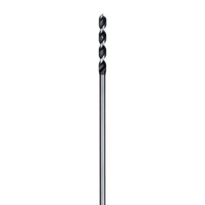
Once you drill through the wall, floor or other surface, you insert a wire into the small hole in the bit and use the bit to draw it back through the hole you bored.

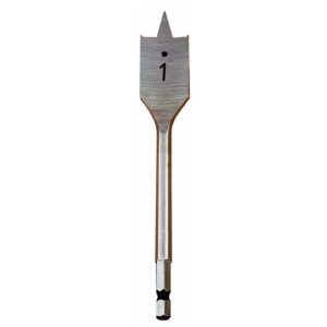
Spade Bit – A spade bit, also known as a paddle bit, bores large-diameter holes — up to 1-1/2 inches in diameter — in wood. It has a flattened blade with a sharp point that helps position and steady the bit. Some spade bits have points at the two edges that help create a neater hole and exit point.

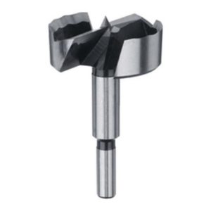
Forstner Drill Bit – A Forstner bit bores smooth, clean holes in wood. You can use it to create flat-bottomed holes — such as for receiving dowels. The design also allows you to overlap holes. A point helps you to position the bit precisely on the workpiece. Pull the bit out regularly to clear away chips and dust as you work. A hand-held drill may not always give you the force or control you need to use a Forstner bit, so a drill press is a better option for some applications.

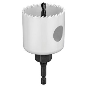
Hole Saw – A hole saw drills large holes — such as for installing door hardware or creating a pass-through for wiring. A hole saw creates a plug of waste material; a cut-out in the side of the saw cylinder allows you to push it out. Typically, a hole saw attaches to an arbor or mandrel which includes a shank. The arbor also holds a pilot bit for centering and steadying the cutting blade. Some smaller hole saws have a built-in shank and don’t use a pilot bit.

bi-metal hole saw cuts through wood and metal. A hole saw with a carbide edge works on heavier materials such as ceramic tile and masonry. A hole saw with a diamond edge also works on tile and masonry, but cuts faster than carbide models.

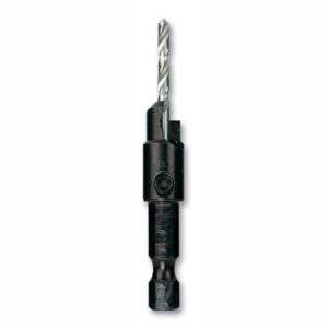
Countersink Drill Bit – A countersink bit — also called a screw pilot bit — is a specialty bit for drilling in wood. In a single action, the bit can drill pilot, counter sink and counter bore holes, allowing you to countersink a fastener and install a plug over the fastener head.

Plug Cutter – A plug cutter bores holes in wood, creating wood plugs for use in concealing recessed fasteners.

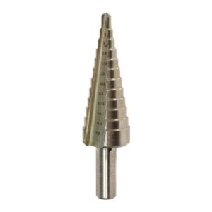
Step Drill Bit – A step bit is designed primarily for drilling in thin — up to 1/4 inch — metal, but will work with wood. The stepped design allows you to use a single bit to drill holes with different diameters. Often the diameter of each step is etched into the bit. You can also use this type of bit to deburr holes, clearing away waste material.

Tile Drill Bit – A tile bit uses a carbide tip to drill into some types of tile while reducing the chance of chips and cracks. Check the packaging to determine the tile it can drill.

Masonry Drill Bit – A masonry bit drills into tough materials such as concrete, brick and other masonry. Some work with a standard corded or cordless rotary drill, but those designed for use with a rotary hammer or hammer drill can bore into masonry more effectively. The hammering action of the tool drives the carbide tip into the material while the rotating action channels away debris along the flutes.
Other Bit Options – In addition to more common drill bits, there are other options and accessories:

  • Drill saw bits cut irregular holes and contours in wood and metal.
  • Pocket hole bits are included with pocket hole jigs. They allow you drill angled holes that accept screws for making wood joints.
  • Scaling chisels work in rotary hammers or hammer drills for chiseling, scaling and chipping masonry.

  • Depth stops prevent drilling beyond a predetermined depth.
  • Driver bits and bit holders work on a drill / driver to install or remove fasteners.
  • Drill bit extensions give your drill a longer reach.
  • Screw or bolt extractors work with a reversible drill / driver to back out damaged fasteners.
  • Right-angle attachments let you drill and drive in areas where a drill won’t fit.
  • Drill / driver bit sets collect various sizes and styles of bits in a convenient case.
04 Sep

Fettling with the 2005 Roadster Air Conditioner

It’s hot in Florida and most Morgan outings are top down.  But when it rains, and it does that daily, you have to put the top up.   Being in a Morgan with the top up, in Florida, is hot, very hot and humid.  But, I have air conditioning in the Roadster.  Yeah, right!

Well, the Roadster air conditioner is the subject of many jokes, and none of them are good.  If Morgan didn’t provide air conditioning, we would have suffered on, as we had before, but since the car supposedly came with ‘Air Conditioning’ we thought we were saved.   Not so.  It doesn’t work and if it does, it doesn’t work very well.

Turning On the 2005 Roadster Air Conditioning

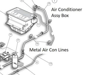
The actual air conditioner lines are high pressure lines and are metal.

They go into an air condition assembly box on the car’s firewall.  This assembly box also houses the car’s heater core (sort of looks like a small radiator) and the heater / air conditioning fan.  The assembly box is covered with some sort of temperature insulating material that is silver-ish.

There is a knob about the size of a nickel near the upper right corner of the air condition assembly box (labeled as Condenser Knob, above, and shown as a red dot.)  This knob is supposed to be fully rotated clockwise.  This insures the air conditioning ‘compressor’ is not turned OFF.  It is rumored that some cars simply had this knob set somewhat counter-clockwise and the air conditioning didn’t work.

Also, inside the car, there is large rotating knob under the dash on the passenger side (LHD) that goes from Hot (Marked in RED) to Cold (Marked in BLUE).  There is also a switch under the dash on the drivers’ side (LHD) labeled with a snow flake (for air conditioning).  One side of the switch shows a vertical bar ‘|’ for ON and the other an ‘O’ for OFF.

  • Rotate the ‘compressor’ knob (the small knob on the outside of the air conditioner assembly box.) fully clockwise.
  • Rotate the large knob (inside the car, under the dash) to the BLUE side
  • Turn the air conditioning switch (inside the car, under the dash) to the ON position (e.g. with the vertical bar ‘|’ for ON).
  • Turn on the fan switch, which is inside the car, on the dash, to low or high.  (It is a two position switch.)

When I do all this, I get semi-cool air blowing into the cockpit.  Certainly, insufficient for the Florida heat and humidity.  It is not new car cold air, more like really old car cool air (someone said tepid).

So What Now?

I tried starting the air conditioning a few times, hoping for a different outcome each time.  Nope the same each time, nadda, still tepid air.

I studied the schematics and stared at the car.  I found a few things I thought I could do.  There are two coolant hoses taking hot coolant from the engine, running it through the heater core (little radiator) to provide the heat for the heater.  (They are shown in purple in the schematic above.)

The fan (switch to turn the fan on and off is located on the dash) blows air through this hot heater core into the car’s cockpit.  The air blown by the fan comes from the hot engine air leaving the forward bonnet louvers and then goes back into the engine bay via the rearward (near the windshield) louvers on the bonnet.  This air then goes into the top of the air conditioning assembly box.

This is the air that is used by the heater / air conditioning systems.  Hot air is fine for the heater but isn’t too good for the air conditioner.

Also, having these hot coolant lines and this hot heater core in the air condition assembly box cannot be good for getting cold air into the cockpit either.

Fixing the air flow looks to be somewhat arduous, at least in my simple mind, however eliminating the hot coolant hoses feeding the heater core looks doable.  So that is what I did.

Tools Needed

All this is really just to loosen and tighten hose clamps.  Your car may have different hose clamps and require different tools.  Well, the pry bar gave me some leverage with sticky hoses.

  • 1/4 inch drive ratchet
  • 6 inch extension for 1/4 inch drive ratchet
  • 7mm Socket (1/4 inch drive)
  • 8mm Socket (1/4 inch drive)
  • Slotted Screw Driver
  • Philips Head Screw Driver
  • Pry Bar
  • 90 degree ¾ inch (outside diameter) brass hose coupling (~$3 at Lowes)

Steps

The hardest part of this task is getting access to the heater core supply and return coolant hoses where they connect into the air conditioner assembly box.  Once you have access it is simply the matter of removing the two hose clamps that hold the hoses on the air conditioning assembly box and then joining the two hoses together with a 3/4 inch coupling.

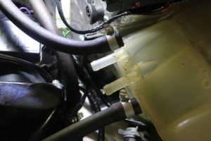
  • Remove the two small overflow tank hoses. Remove the hose clamps using slotted screwdriver.  See picture of overflow tank with hoses removed, below.

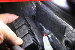
  • Relocate electrical relays attached via an attached Velcro patch. Simply pull Velcro away.  See picture of velcro on electrical relays and on air conditioner assembly box, below.

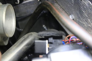
  • Remove the large Air Flow hose. Again, remove the hose clamps and pull.  The hose is fairly pliable.  See picture of the void left when the  the large air flow hose is removed, below.

  • Now you can access the two hoses going into the air conditioning assembly box that carry the hot coolant water.  Note: When you pull these away, you will have some spillage of coolant as the heater core is most likely full.  It isn’t very much however.
  • Simply connect the two hoses together using the metal coupling (I tried it with a straight coupling and it was too difficult to get the hoses in the correct position, so I opted for a 90° angled coupler. This was much easier.) I found the coupling at the local home improvement store.  I suspect they are everywhere.  This removes  the flow of hot coolant from the heater core and of course, disables the heater. Now just put everything back.
  • Put the large Air Flow hose back on. Again, use the hose clamps on each end and push and pull to get it set on each end.  Then tighten the hose clamps.
  • Put the electrical relays back onto their Velcro patch.
  • Finally, reconnect the two overflow tank hoses.
  • Re inspect to make sure everything is reconnected and tightened up.
  • Take the car for a test drive.

The Result 

I think this simple modification greatly improved the performance of my air conditioning.  It is still not extremely cold, but it is quite a bit cooler than before.  Now, I suspect everyone’s car is different (these are Morgans, of course) so your results may vary.  I also think that reworking the air flow, as discussed above, will improve the air conditioning some more.

I believe a more elegant solution that addresses not only the hot coolant hoses, but also the hot air flow issues and a solution that doesn’t disable the heater, is in the works.  I will probably opt for that solution when it is here and tested, however until then, this is about ‘as good as it gets’.

Cheers,  Mark

30 Aug

WHITWHAT? THE WHITWORTH SYSTEM (Moss Motors)

[It happens to me all the time.  The wrench won’t fit, it’s too small, so I get the next larger one and it won’t fit either, it’s too large.  Nothing in between?  What now, darn, it’s probably ‘Whitworth’.  If you play with old British cars, you have most likely run into this situation.  An interesting read with the morning coffee.  Unless you abhor auto parts??  Mark]

Most of us think of car parts in terms of carburetors, engines, transmissions, brakes, and so on. The most common part in any car isn’t really noticed at all until you take one apart. Even then you don’t think much about it until it comes time to put the car back together again and, suddenly, you discover that you don’t have quite as many as you should. I’m talking about the nuts and bolts that hold a car together.

To make matters more interesting, a good many of the cars we deal with don’t use nuts and bolts that can be purchased from the corner hardware store. Much maligned and misunderstood, the Whitworth hardware used on older British cars has an interesting history.

Threaded fasteners go back a long way. In 1568, the first practical screw cutting machine was invented by a French mathematician named Jacques Besson. After that, things took off…after a fashion. By 1611 the idea had caught on in England well enough for it to be mentioned in a book, the significant point being that the companion piece to any screw—the nut—was mentioned as well. While the concept was basically sound, in practice there were a few bugs to be worked out. In general, a screw is a threaded fastener that is turned into a threaded hole; a bolt passes through the hole and is secured with a nut on the other side. In the 1600’s putting something together was a real chore. Once you found a bolt you liked, you had to find a nut, and that was a matter of chance [Still is, in my garage . . . . Mark] since nobody had any idea of making the treads the same. Once you found a nut that fit, (well, sort of) the nut and bolt were tied together with string. Since the threads on any one fastener were unique, taking something apart and putting it back together again could be a lifetime occupation. Just be thankful that the car had not yet been invented.

This happy chaos continued until well into the industrial revolution, when Henry Maudslay perfected a lathe that made it possible to adjust the thread pitch of a screw. This made it possible to make large numbers of identical screws. The idea of making the bolts for one machine all the same seems to have caught on. at least with the folks who had to put them together.

Making threaded fasteners on a lathe is time consuming, and therefore expensive. In 1850 a man from New York named William Ward perfected a system for forming the threads on a bolt by heating it to 1600 degrees Fahrenheit, and then rolling it between two grooved dies. The grooves on the flat dies were forced into the bolt, and the threads were formed as the bolt rolled between the fixed and the moving die.

This same basic system is used today, the only difference being that the bolts are not heated before being rolled. “Cold” forming produces much more uniform threads, allowing closer tolerances, and because the bolts are not heated, they are stronger.

Even today, the development of this technology would not really matter if there were no national or international standards for threads on screws and bolts. We would still be buying nuts and bolts as matched pairs. The man responsible for the development of the first standards for the production of threaded fasteners Is none other than Joseph Whitworth. [Who knew?? Mark] In 1841, his paper, “A Uniform System of Screw Threads”, set forth a concept that was to revolutionize manufacturing.

His idea was simple:

  1. Each diameter of bolt or screw will have its own number of threads per inch (TPI)
  2. The angle between the side of one thread and the adjacent thread should be 55°.
  3. Both the crest and root of each thread should be rounded.
  4. The relationship of the pitch to the radius of the rounded portion of the thread is defined by a ratio of l/6th; in other words, the radius r = (1/6) x (pitch).

Finally, there was a system. If adopted, that would allow the fasteners used on one type of machine to be replaced with another “standard” fastener. The logic was hard to beat, and England adopted the system to the extent that by 1881 it was the effectively the British standard.

The Whitworth System was used as proposed for bolts and screws from 1/8″ to 4 1/4″ in shank diameter up to 1908, when an additional thread form was proposed—British Standard Fine (BSF). Presented by the British Engineering Standards Association, BSF was identical to the original Whitworth form except that the pitch was finer—meaning more threads per inch. Now a bolt with a diameter of 1/4 inch could have either 20 threads per inch (BSW) or 26 (BSF). The advantage of the finer thread pitch is two fold. A fine thread bolt is about 10% stronger than a coarse thread bolt of the same size and material.  [I knew this but I didn’t know why I knew this.  Mark]  Fine threaded fasteners also have greater resistance to vibration. Those of you who have worked on cars with Whitworth hardware will have noticed that almost all the hardware is BSF for these reasons. Why use any coarse threaded bolts at all? Coarse thread fasteners are well suited for use in tapped holes in material softer than the bolt (such as studs in aluminum cylinder heads), and they are easier to assemble. It’s almost impossible to cross thread a coarse threaded fastener by hand.

For sizes smaller than 1/8″, the British adopted a Swiss Standard thread form for small screws and called it British Association Thread (BA). This thread form was adopted in 1903. Like the Whitworth form, it has rounded crests and roots, but the angle between adjacent faces of the screw’s threads Is 47 1/2°. Instead of being sized by fractions of an inch, they are numbered OBA, 1BA, 2BA and so on up to 22BA. For some reason, the larger the number, the smaller the screw. Other than that, the system is analogous to our “machine screw” system where numbers are used (e.g. #6, #8, #10).

A question often asked (well, once in a while anyway) is why didn’t the US adopt the Whitworth System? As it turns out, we did. By 1860, most of Europe and the US were using the system. In 1864, however, the move to establish a “National” thread system was under way. William Sellers was instrumental in persuading the Franklin Institute in Philadelphia to set up a committee whose prime goal would be to set up national (meaning American) standards. Sellers, who made machine tools, was dissatisfied with the Whitworth System on several points: The 55° angle was hard to gauge and the rounded threads caused an uncertain fit between the nut and bolt. He also argued that the rounded threads were weaker than a system he proposed where the angle between the opposing faces was 60° (not Whitworth’s 55°), and the crests and roots were flattened. The Franklin Institute adopted Seller’s system, and by 1900 it was in use throughout the US and much of Europe. The American system had both line and coarse threads called, logically enough, American National Fine (ANF) and American National Coarse (ANC).

The Whitworth system is further complicated by its tool size designations. American tools (and European for that matter) are sized by the head of the bolt or the size of the nut. A 1/2″ wrench fits a bolt with a head 1/2″ across. A Whitworth wrench is sized according to the diameter of the shank of the bolt, not the head. A 1/4 W (Whitworth) wrench is actually a bit larger than a 1/2″ American wrench—0.525″ to 0.500″. As if that wasn’t enough, in 1924 it was decided that the heads of the Whitworth bolts were too large, so they were down-sized.

The “new” bolts and nuts were made so that the old tools could still be used, but on different bolts. The old 3/8W wrench now fit the 7/16″ bolt. To enable the tools to be used easily, they are marked with both sizes. The old size, which stands for the diameter of the bolt’s shank, is marked with a “W”. The new size is marked with a “BS”, which stands for the bolt size and consequently the new wrench size. For example, the old 3/8W wrench also fits the “new” 7/16″ bolt and is therefore also marked “7/16 BS”. The head of the bolt it fits is 0.600″ across the flats, larger than 19/32″ but smaller than 5/8″.  [I am so glad there isn’t a test at the end!  Mark]

Because the wrenches are unique, there are no American counterparts. Use of the closest American wrench will often result in the rounding of corners and the springing of the wrench jaws.

The Whitworth System, with its associated BS thread system, was in use by British automobile manufactures until 1948, when Canada, the US, and the United Kingdom adopted a “Unified Thread System” that incorporated features of Seller’s and Whitworth’s systems. Actually, the push to standardize an international thread system was initiated during the First World War. The necessity for a system that both American and English manufactures could use was a direct result of the war effort. The fact that the allies shared much of the same machinery and equipment made interchangeable parts essential. The issue was the subject of various international conferences from 1918 to 1948, with the 2nd World War playing the role of catalyst for the adoption of the Unified system. The Unified System was adopted by the British automobile industry on a large scale in 1956, when most of the common fasteners on the cars built that year were of the Unified Thread System. The fact that the major market for these cars was in the US was no doubt a major factor in the decision. The Unified System is basically the same as the American system in use—the two thread systems were American National Coarse (ANC) and American National Fine (ANF). They became the Unified coarse and fine. A few related industries, notably SU, did not make the switch, and used Whitworth and BS hardware until they ceased production.

The Unified System was not destined to last. Having seen that everyone could change over from one system to another, the International Standards Organization launched a campaign to replace the Unified system with a version of the metric system that originated in Europe. It has been slow going. Since 1966 there has only been a partial changeover to the ISO metric system in the American and British automotive industries.

The Whitworth system should not be viewed as a stumbling block invented by the English to keep us from putting their cars back together again once we’ve managed to take them apart. I don’t believe it has anything to do with our minor disagreement back in 1776 either. The Whitworth system made it possible to manufacture complex machinery on a large scale, and it made it possible to work on that machinery without having a full-time clerk keeping track of the different nuts and bolts. Each system takes some special wrenches and sockets, and you might have to think for a minute or two about which wrench to use, but heck, if it were easy, anybody could work on these cars.

16 Jul

Yes, You Want One – An ‘Anti-Drain-Back-Valve’ in Your Oil Filter

[This treatise was taken from a number of sites on the internet (and then edited some) and seems to be good guidance relative to the need for the anti-drain-back-valve in your Morgan’s oil filter.  The question has come up a few times and we have tried to answer it, but haven’t really been convincing.  This seems to do it.  FYI, Race Cars with oil preheaters, etc., may have different requirements.  Mark]

Your Engine ‘oil filter’ is a very important component; it traps dirt and debris, preventing them from circulating throughout the engine.  This protects vital internal parts such as bearings, journals, and cylinder walls.

Another way the oil filter protects and helps lubricate the engine is using an anti-drain back-valve.  This valve is predominantly used within the spin-on versions of today’s oil filter and not a part of the older style of cartridge style filters (such as the original style 1950s – 1960s Plus 4s filters).  Although you may not have heard of it before or know what it does, this valve is extremely important.  Extensive engine damage can result if it isn’t working properly.

Oil filter design

The oil filter’s design might seem simple, but there is a lot more to an oil filter than you might think. Before delving into the details of what damage can be caused by a faulty anti-drain back valve, it’s a good idea to know how a car oil filter works. Typical oil filter components include the following:

  • Tapping or cover plate: This is the plate at the bottom of the filter.  It serves as an entry and exit point for oil. It also contains a threaded center hole, which allows the filter to attach to the engine.
  • Filter medium: Dirt and debris are trapped in the filter medium.  Typically, it is constructed from microscopic cellulose fibers along with synthetic fiber.  It is then saturated with resin for added strength.  The filter medium is folded into pleats to create a greater surface area.
  • Center steel tube: The center steel tube provides a structure for the filter.  It also allows filtered oil to return to the engine.
  • Relief valve: The relief valve opens when oil pressure is too great due to clogged filter media.  This allows unfiltered oil to exit through the center tube to prevent engine starvation.
  • End disc: Some oil filters use an end disc to prevent unfiltered oil from leaking into the center tube.  Others use a sealant instead.
  • Retainer: As the name implies, the retainer keeps the filter medium and end disc tight against the tapping plate.
  • Anti-drain back valve: The anti-drain-back-valve prevents oil from draining out of the filter when the engine is turned off.

Engine damage caused by a faulty anti-drain-back-valve

During an oil change, it’s recommended you put fresh oil in the new filter before installing it.  This is so oil is available to the engine as soon as it’s started.

The anti-drain-back-valve serves a purpose that’s like this oil change strategy.  Every time your engine is shut off, the valve keeps oil from draining out of the filter.  This allows the engine to receive oil immediately upon start up.

A faulty anti-drain-back-valve lets oil drain back into the engine.  This keeps oil from getting to the engine when it’s first started.  The result is engine wear and eventual failure from lack of lubrication.  Low-quality oil filters often have a poorly designed anti-drain-back-valve that doesn’t work properly.

Don’t settle for low-quality oil filters

The best way to avoid anti-drain back problems is to use a high-quality filter.  A good filter usually has a robust anti-drain-back-valve, designed to protect your Morgan’s engine.

04 Jul

On-board diagnostics (OBD) (Wikipedia and Morganatica)

On-board diagnostics (OBD) is an automotive term referring to a vehicle’s self-diagnostic and reporting capability. OBD systems give the vehicle owner or repair technician access to the status of the various vehicle subsystems. The amount of diagnostic information available via OBD has varied widely since its introduction in the early 1980s versions of on-board vehicle computers.  Early versions of OBD would simply illuminate a malfunction indicator light or “idiot light” if a problem was detected but would not provide any information as to the nature of the problem.

Modern OBD implementations use a standardized digital communications port to provide real-time data in addition to a standardized series of diagnostic trouble codes, or DTCs, which allow one to rapidly identify and remedy malfunctions within the vehicle.

[ODB implementations have been mandated in Europe since 2001 so it is believed that all Morgans since that date, e.g. late model Plus 8s, Roadsters and Aero 8, as well as the new ‘component’ Morgans expected in 2018 will have OBD capabilities.  Consumer level ODB readers are available just about everywhere and you can buy them to assist you in troubleshooting any faults.  Dedicated automotive repair facilities will most likely utilize more sophisticated ‘OEM-like’ ODB code readers.  Mark]

EOBD

The EOBD (European on board diagnostics) regulations are the European equivalent of OBD-II, and apply to all passenger cars first registered within EU member states since January 1, 2001.

The technical implementation of EOBD is essentially the same as OBD-II, with the same SAE J1962 diagnostic connector and signal protocols being used.

Each of the EOBD fault codes consists of five characters: a letter, followed by four numbers. The letter refers to the system being interrogated e.g. Pxxxx would refer to the powertrain system. The next character would be a 0 if complies to the EOBD standard. So it should look like P0xxx.

The next character would refer to the sub system.

  • P00xx – Fuel and air metering and auxiliary emission controls.
  • P01xx – Fuel and air metering.
  • P02xx – Fuel and air metering (injector circuit).
  • P03xx – Ignition system or misfire.
  • P04xx – Auxiliary emissions controls.
  • P05xx – Vehicle speed controls and idle control system.
  • P06xx – Computer output circuit.
  • P07xx – Transmission.
  • P08xx – Transmission.

List of OBD Fault Codes

P1000 OBD-II Monitor Testing Incomplete
P1001 KOER Test Cannot Be Completed
P1039 Vehicle Speed Signal Missing or Improper
P1051 Brake Switch Signal Missing or Improper
P1100 Mass Air Flow Sensor Intermittent
P1101 Mass Air Flow Sensor out of Self-Test Range
P1112 Intake Air Temperature Sensor Intermittent
P1116 Engine Coolant Temperature Sensor is out of Self-Test Range
P1117 Engine Coolant Temperature Sensor Intermittent
P1120 Throttle Position Sensor out of range
P1121 Throttle Position Sensor Inconsistent with Mass Air Flow Sensor
P1124 Throttle Position Sensor out of Self-Test Range
P1125 Throttle Position Sensor Intermittent
P1127 Heated Oxygen Sensor Heater not on During KOER Test
P1128 Heated Oxygen Sensor Signals reversed
P1129 Heated Oxygen Sensor Signals reversed
P1130 Lack of Upstream Heated Oxygen Sensor Switch – Adaptive Fuel Limit – Bank No. 1
P1131 Lack of Upstream Heated Oxygen Sensor Switch – Sensor Indicates Lean – Bank No. 1
P1132 Lack of Upstream Heated Oxygen Sensor Switch – Sensor Indicates Rich – Bank No. 1
P1135 Ignition Switch Signal Missing or Improper
P1137 Lack of Downstream Heated Oxygen Sensor Switch – Sensor Indicates Lean – Bank No. 1
P1138 Lack of Downstream Heated Oxygen Sensor Switch – Sensor Indicates Rich – Bank No. 1
P1150 Lack of Upstream Heated Oxygen Sensor Switch – Adaptive Fuel Limit – Bank No. 2
P1151 Lack of Upstream Heated Oxygen Sensor Switch – Sensor Indicates Lean – Bank No. 2
P1152 Lack of Upstream Heated Oxygen Sensor Switch – Sensor Indicates Rich – Bank No. 2
P1157 Lack of Downstream Heated Oxygen Sensor Switch – Sensor Indicates Lean – Bank No. 2
P1158 Lack of Downstream Heated Oxygen Sensor Switch – Sensor Indicates Rich – Bank No. 2
P1220 Series Throttle Control fault
P1224 Throttle Position Sensor B out of Self-Test Range
P1230 Open Power to Fuel Pump circuit
P1231 High Speed Fuel Pump Relay activated
P1232 Low Speed Fuel Pump Primary circuit failure
P1233 Fuel Pump Driver Module off-line
P1234 Fuel Pump Driver Module off-line
P1235 Fuel Pump Control out of range
P1236 Fuel Pump Control out of range
P1237 Fuel Pump Secondary circuit fault
P1238 Fuel Pump Secondary circuit fault
P1250 Lack of Power to FPRC Solenoid
P1260 Theft Detected – Engine Disabled
P1270 Engine RPM or Vehicle Speed Limiter Reached
P1288 Cylinder Head Temperature Sensor out of Self-Test Range
P1289 Cylinder Head Temperature Sensor Signal Greater Than Self-Test Range
P1290 Cylinder Head Temperature Sensor Signal Less Than Self-Test Range
P1299 Cylinder Head Temperature Sensor Detected Engine Overheating Condition
P1309 Misfire Detection Monitor not enabled
P1351 Ignition Diagnostic Monitor circuit Input fault
P1352 Ignition Coil A – Primary circuit fault
P1353 Ignition Coil B – Primary circuit fault
P1354 Ignition Coil C – Primary circuit fault
P1355 Ignition Coil D – Primary circuit fault
P1356 Loss of Ignition Diagnostic Module Input to PCM
P1358 Ignition Diagnostic Monitor Signal out of Self-Test Range
P1359 Spark Output circuit fault
P1364 Ignition Coil Primary circuit fault
P1380 VCT Solenoid Valve circuit Short or Open
P1381 Cam Timing Advance is excessive
P1383 Cam Timing Advance is excessive
P1390 Octane Adjust out of Self-Test Range
P1400 Differential Pressure Feedback Electronic Sensor circuit Low Voltage
P1401 Differential Pressure Feedback Electronic Sensor circuit High Voltage
P1403 Differential Pressure Feedback Electronic Sensor Hoses Reversed
P1405 Differential Pressure Feedback Electronic Sensor circuit Upstream Hose
P1406 Differential Pressure Feedback Electronic Sensor circuit Downstream Hose
P1407 EGR No Flow Detected
P1408 EGR Flow out of Self-Test Range
P1409? EGR Vacuum Regulator circuit malfunction
P1409? Electronic Vacuum Regulator Control circuit fault
P1410 EGR Barometric Pressure Sensor VREF Voltage
P1411 Secondary Air is not being diverted
P1413 Secondary Air Injection System Monitor circuit Low Voltage
P1414 Secondary Air Injection System Monitor circuit High Voltage
P1442 Secondary Air Injection System Monitor circuit High Voltage
P1443 Evaporative Emission Control System – Vacuum System – Purge Control Solenoid or Purge Control Valve fault
P1444 Purge Flow Sensor circuit Input Low
P1445 Purge Flow Sensor circuit Input High
P1450 Inability of Evaporative Emission Control System to Bleed Fuel Tank
P1451 EVAP Control System Canister Vent Solenoid Circuit Malfunction
P1452 Inability of Evaporative Emission Control System to Bleed Fuel Tank
P1455 Substantial Leak or Blockage in Evaporative Emission Control System
P1460 Wide Open Throttle Air Conditioning Cutoff circuit malfunction
P1461 Air Conditioning Pressure Sensor circuit Low Input
P1462 Air Conditioning Pressure Sensor circuit high Input
P1463 Air Conditioning Pressure Sensor Insufficient Pressure change
P1464 ACCS to PCM High During Self-Test
P1469 Low Air Conditioning Cycling Period
P1473 Fan Secondary High with Fans Off
P1474 Low Fan Control Primary circuit
P1479 High Fan Control Primary circuit
P1480 Fan Secondary Low with Low Fans On
P1481 Fan Secondary Low with High Fans On
P1483 Power to Cooling Fan Exceeded Normal Draw
P1484 Variable Load Control Module Pin 1 Open
P1500 Vehicle Speed Sensor Intermittent
P1501 Programmable Speedometer & Odometer Module/Vehicle Speed Sensor Intermittent circuit-failure
P1502 Invalid or Missing Vehicle Speed Message or Brake Data
P1504 Intake Air Control circuit malfunction
P1505 Idle Air Control System at Adaptive Clip
P1506 Idle Air Control Over Speed Error
P1507 Idle Air Control Under Speed Error
P1512 Intake Manifold Runner Control Stuck Closed
P1513 Intake Manifold Runner Control Stuck Closed
P1516 Intake Manifold Runner Control Input Error
P1517 Intake Manifold Runner Control Input Error
P1518 Intake Manifold Runner Control fault – Stuck Open
P1519? Intake Manifold Runner Control Stuck Open
P1520? Intake Manifold Runner Control circuit fault
P1519? Intake Manifold Runner Control fault – Stuck Closed
P1520? Intake Manifold Runner Control fault
P1530 Open or Short to A/C Compressor Clutch circuit
P1537 Intake Manifold Runner Control Stuck Open
P1538 Intake Manifold Runner Control Stuck Open
P1539 Power to A/C Compressor Clutch circuit Exceeded Normal Current Draw
P1549 Intake Manifold Temperature Valve Vacuum Actuator Connection
P1550 Power Steering Pressure Sensor out of Self-Test Range
P1605 PCM Keep Alive Memory Test Error
P1625 Voltage to Vehicle Load Control Module Fan circuit not detected
P1626 Voltage to Vehicle Load Control Module circuit not detected
P1650 Power Steering Pressure Switch out of Self-Test Range
P1651 Power Steering Pressure Switch Input fault
P1700 Transmission system problems
P1701 Reverse Engagement Error
P1702 Transmission system problems
P1703 Brake On/Off Switch out of Self-Test Range
P1704 Transmission system problems
P1705 Manual Lever Position Sensor out of Self-Test Range
P1709 Park or Neutral Position Switch out of Self-Test Range
P1710 Transmission system problems
P1711 Transmission Fluid Temperature Sensor out of Self-Test Range
P1713
thru
P172 Transmission system problems
P1729 4×4 Low Switch Error
P1740 Transmission system problems
P1741 Torque Converter Clutch Control Error
P1742 Torque Converter Clutch Solenoid Faulty
P1743 Torque Converter Clutch Solenoid Faulty
P1744 Torque Converter Clutch System Stuck in Off Position
P1745 Transmission system problems
P1746 Electronic Pressure Control Solenoid – Open circuit
P1747 Electronic Pressure Control Solenoid – Short circuit
P1749 Electronic Pressure Control Solenoid Failed Low
P1751 Shift Solenoid No. 1 Performance
P1754 Coast Clutch Solenoid circuit malfunction
P1756 Shift Solenoid No. 2 Performance
P1760 Transmission system problems
P1761 Shift Solenoid No. 3 Performance
P1762 Transmission system problems
P1767 Transmission system problems
P1780 Transmission Control Switch circuit is out of Self-Test Range
P1781 4×4 Low Switch is out of Self-Test Range
P1783 Transmission Over-Temperature Condition
P1784 Transmission system problems
P1785 Transmission system problems
P1786 Transmission system problems
P1787 Transmission system problems
P1788 Transmission system problems
P1789 Transmission system problems
P1900 Transmission system problems

[I haven’t personally verified that each of these codes exist or are as specified, so if you do find inconsistencies, please let me know.   Mark]

22 Jun

Castrol R (Motorsport Magazine)

[We have had some questions and discussion on this topic but this is the first concise article I have been given that clearly addressing the ‘why.’  Cheers, Mark]

It is curious that we understand much better than its inventors the way Castrol R works, yet take it for granted. Keith Howard redresses that balance

In the case of Sir Charles Cheers Wakefield, later Baron Wakefield of Hythe, the sweet smell of success was more than a metaphor. You still catch the scent of the substance that made his company a household name in the early 1900s wherever older racing engines are exercised: that distinctive, heady perfume of Castrol R. Although castor oil, the origin of the smell, was still the purgative bane of many a childhood when C C Wakefield & Co introduced its Castrol range in 1909 (the name being a contraction of castor oil), to high performance engines on the road and in the air it was to become a more welcome part of the diet.

The story begins in 1899 when, having spent 15 years working for the London office of Vacuum Oil Company of Rochester, NY, later to metamorphose into Mobil, Charles Wakefield resigned his position as general manager and determined to strike out on his own. It was an auspicious time to be doing so. Within four years the Wright Brothers would take tentatively to the air, followed albeit somewhat belatedly by compatriot Samuel Franklin Cody at Famborough in 1908. A year later Louis Bleriot flew the English Channel and, five years after that, storm clouds over Europe would spur a period of unprecedented aircraft development effort. On the ground, progress was scarcely less momentous as the horseless carriage progressed from being a curiosity and plaything into an increasingly practical mechanism, as well as another vehicle of human endeavour and national rivalry.

Charles Wakefield wasn’t slow to realise that here lay both an important new market for lubricating oils and, just as significantly, a whole new marketing opportunity also. The world was agog at the daredevil exploits unfolding on land and in the air; having your product name attached to such derring do was a golden opportunity to exploit what today we would call product placement. So Charles Wakefield determined to produce a new breed of oil for this new breed of machine, and make certain that the world knew of it.

Engine oil development, like engine development itself, was then in its infancy. Today’s world of multigrade and synthetic oils was a long way off. Prior to the sinking of the first petroleum well in 1859, engineers had had to use animal and vegetable fats and oils for lubrication, but these proved far from ideal at the extremes of temperature involved in the internal combustion engine. As every cook knows, fats and oils thicken when you put them in the fridge and leave gummy, varnish-like deposits when you heat them in a pan. This same behaviour in an engine made cold cranking difficult on startup, while oxidation of the lubricant at combustion temperatures could, literally, gum up the works.

Mineral oils relieved these limitations, even in their early forms offering a level of thermal and oxidative stability traditional lubricants couldn’t match. But they were far from perfect In particular they lacked what, at the time, was termed “oiliness”, the ability to adhere to metal surfaces in a thin, continuous film. Wakefield researchers found that whereas castor oil coated a hot metal surface, mineral oil tended to pool on it, leaving areas of metal exposed.

Today we have a much better understanding of why this happens. Castor oil is composed almost entirely of triglyceride fatty acids, of which ricinoleic glycerides form by far the largest proportion (typically around 86 per cent). Fatty acids are polarised molecules comprising an oily, hydrophobic (water-hating) head and a hydrophilic (water-loving) tail; the hydrophilic ends of castor oil molecules are adsorbed to the metal surface, leaving the oily heads protruding.

The result is that castor oil provides excellent boundary lubrication, much better than that achieved by early mineral alternatives. In hydrodynamic bearings, like crankshaft bearings, where a relatively thick layer of oil is established, this offers no benefits. But where the oil layer is thin — on cylinder walls and cam lobes, for instance — it ensures a higher level of scuff resistance.

Mixing castor and mineral oil therefore seemed a good idea in the early 1900s, but the two are not readily miscible. What Wakefield researchers discovered was that a surprisingly small proportion of castor oil — as little as 0.7 per cent — was sufficient to confer its high film strength on the mix, and thus Wakefield Motor Oil (Castrol Brand) was born. In fact, five variants were introduced initially for different applications, Castrol R being the flagship product intended for aero and racing engines. Wakefield & Co’s core business was — and in the immediate future, would remain — lubricants for the railways and industrial customers, but it was Castrol Brand that was to carry the company name to the four corners of the globe.

Success was almost immediate. In October 1909, Britain’s first aviation prize, the Inauguration Cup, was won by Frenchman Leon Delagrange using Castrol oil. Following which, on land and in the air, the litany of Castrol successes encompasses many of the most significant events in aviation and motoring history, including Britain’s winning of the Schneider Trophy three times in a row with the R J Mitchell designed, Rolls-Royce powered Supermarine S5, and most of the World Land Speed Records established during the highly competitive inter-war years. In the Great War, Castrol R even came to the attention of Kaiser Wilhelm II, achieving almost ‘secret weapon’ status when it was discovered that a captured British aircraft could operate at considerably higher altitudes than German equivalents due to its engine oil’s superior low temperature performance.

In the 1920s castor oil was removed from general motoring oils as mineral oil technology advanced, but its superior film strength ensured it a continued role in high performance engines. Only in 1953 was Castrol R superseded by R20, again containing castor oil but this time mixed with a semi-synthetic, and the successes began all over again. Mercedes-Benz immediately chose it for the advanced W196, Fangio scoring a first-time-out victory for both oil and car when he won the French GP in ’54.

Even today castor oil remains the lubricant of choice in certain applications, notably methanol powered two-strokes because of its complete miscibility with alcohol fuels. As a result you don’t have to go to a historic race meeting to catch that distinctive castor aroma. Appropriately, it can even be smelt where enthusiasts fly model aeroplanes.

10 May

Keep it Tight (Grass Roots Motorsports – 5/10/2018)

By J.G. Pasterjak  May 9, 2018

Earlier this year, SCCA Solo Nationals week started off rather promisingly. A third-place trophy in the CAMInvitational gave us high hopes heading into the SCCA Championship event. But our excitement dropped to the ground when our inattention to a single bolt cost us a strong finish.

We want you to learn from our misfortune, so we put together a guide on keeping fasteners fastened.

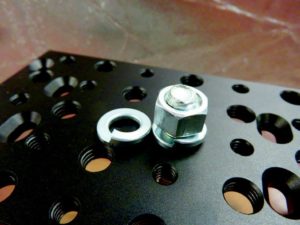
Split Lock Washer

Description: Split lock washers are the most common type of locking device. They’re also one of the least effective, but they’re easy to produce and readily available. Split lock washers are flat washers that have been cut and “twisted” so that they create tension under the bolt head. In theory, this tension applies additional load to the threads and makes them less likely to back out. Typically, however, it takes far less torque to completely compress the washer flat than the fastener needs for proper hold.

Pros: Readily available, inexpensive and ubiquitous.

Cons: Doesn’t really do much.

Should be used when: Loads are light and non-critical and nothing better is available.

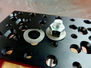
Wave Washers

Description: Wave washers are similar in principal to the split washer, but this is a continuous loop with a “wave” shape that applies tension as the bolt is tightened. Drawbacks are very similar to the split washer, but the wave washer is kinder to the surface and will not leave burrs.

Pros: Does not require a flat washer. Looks neat.

Cons: Similar to split washers. Looks weird.

Should be used when: You have a very light load and don’t want to use an additional flat washer.

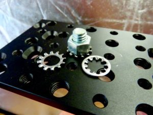
Serrated Washers


Description: Serrated washers are also referred to as “star” washers, which rather accurately describes their appearance. These are available with the “teeth” on either the inner or outside diameter of the washer, and work by physically digging into the underside of the bolt head as well as the (hopefully soft) surface against which they are used.

Pros: Simple. Nice, direct mechanical operation.

Cons: Not terribly strong. Not good on hard surfaces.

Should be used when: You’re putting small fasteners into soft materials (aluminum, plastic, etc.).

Tab Washers

Description: A tab washer is a flat plate that is installed under a bolt head or nut, affixed to another fastener, then bent up to keep the primary fastener from rotating. Cool idea, but there’s an inherent weakness: Any material soft enough to bend will be soft enough to crush under the fastener’s tension. Good thing the tab washer is there to keep the bolt tight, because that tab washer is crushing under the bolt head and trying to make it looser.

Pros: Easy to improvise. Ease of visual inspection.

Cons: Inherently flawed, much like modern country music.

Should be used when: You have nothing left to lose.

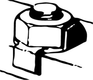
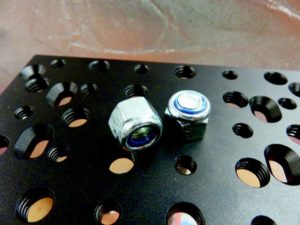
Nylon Collar Lock Nuts

Description: Commonly referred to as “nyloks,” these nuts feature a nylon collar insert that is a smaller diameter than the threads. When the nylon is engaged with the male threads, it forms a compression interface that keeps the fastener from turning on its own.

Pros: Readily available, inexpensive, does not require additional bits of hardware.

Cons: Still somewhat susceptible to vibration loosening, although will rarely back out past the point where initial bolt tension is lost. Should not be heavily reused. Heat can melt the nylon insert.

Should be used when: Whenever you can. Good all-around performer from an effectiveness/ cost/availability standpoint. Everyone’s hardware assortment should include nylon locking fasteners.

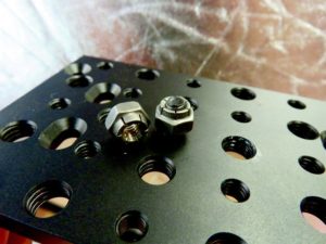
Prevailing Torque Nuts

Description: Picture a regular nut, with regular threads for most of its length, but with an end that has been distorted into (usually) a more triangular shape, or “teeth” that are angled inward. When the nut is applied to the male threads, the force distorts the nut into a round shape, but the inherent tension creates a strong mechanical friction.

Pros: Strong and very vibration resistant. The good ones (mil-spec) are surprisingly reusable and won’t damage the bolt’s male threads.

Cons: This is a kind of specialized bit of hardware, so availability isn’t wide. Cheap ones will be one-time use and could mess up male threads when removed.

Should be used when: You’re rich and can afford the mil-spec stuff. Use prevailing torque nuts when you’d usually use a nylok nut, but high temperatures won’t allow it.

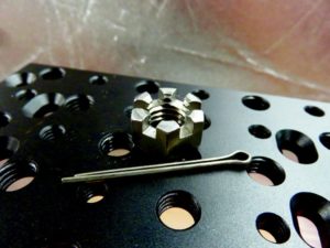
Slotted Beam Stop Nuts


Description: Commonly called castle nuts, these feature a segmented top section through which a cotter pin can be inserted for use on a cross-drilled bolt. A similar-looking arrangement also works like the elastic stop nuts. In this version, the slotted parts are angled inward and create mechanical friction on the fastener when tightened.

Pros: Very positive and visually identifiable locking.

Cons: In some applications, aligning the slots with the hole may result in the application of either too much or not enough torque.

Should be used when: Specific torque isn’t critically important, but retention is.

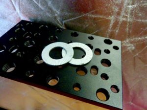
Wedge-Locking Washers

Description: Most commonly referred to as “Nord-Locks,” which is actually a brand name of one of the more common versions, these wedge-locking washers actually feature a two-washer system that uses interlocking plates to create additional friction that prevents rotation. The washers have two toothed surfaces that fit together and provide torque counter to the direction of rotation. Serrated outer surfaces grip the bolt head and surface plate.

Pros: Most vibration-resistant system that doesn’t use an external force (such as safety wire). Can be installed with common tools, just like a regular washer.

Cons: Many times more expensive than regular washers. Serrations will mark surface it mates against.

Should be used when: When you really need resistance to both vibration and rotation and don’t mind the extra cost. Wedge-locking washers are what we chose to lock down our Mustang’s Watts link; for mission-critical fasteners, they’re likely worth the cost.

Diamond-Embedded Friction Washers


Description: As the name implies, and the microscopic closeup shows, these washers are embedded with crushed diamonds, which creates an extremely high-friction mechanical connection. The hardness of diamonds means these work very well on hard surfaces. Most widely used in the aerospace industry and among OEMs for stuff like cam bolts and crankshaft bolts.

Pros: Strong mechanical connection. Works great for hardened surfaces, or surfaces without a lot of inherent friction.

Cons: You’re not going to find these at Ace Hardware. This is specialized stuff with a price to match.

Should be used when: Your ruby washers just don’t have the same panache anymore. Seriously, this is a good product for when you need a high-friction connection, but don’t want to introduce additional pieces as required by the wedge-locks.

Safety Wire

Description: A wire is passed through a drilled hole in the fastener and attached to another hard point to prevent loosening.

Pros: Probably the safest overall solution, both structurally and for ease of visual inspection. Even a mediocre job of safety wiring is stronger than most other things on this list.

Cons: Complex and time consuming. Requires additional specialized equipment and knowledge. Not good for anything that requires frequent removal.

Should be used when: You don’t want something to come off, and you don’t intend to take it off any time soon. See also: every bolt on a helicopter.

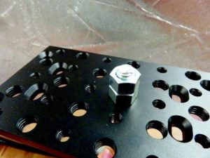
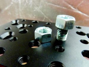
Jam Nuts


Description: Besides sounding like that party band your uncle was in during college that he just won’t shut up about (no, Randy, you never “almost got signed”-let it go already) jam nuts are one of the best “conventional” locking methods around. A jam nut is a second nut that is applied to a bolt’s male threads and then tightened against the first fastener. This produces opposing stresses and increases friction on the threads.

Pros: Easy, cheap and reliable. Jam nuts are a go-to solution that’s easy to implement in the field. Use a nylok jam nut for even more reliability.

Cons: Requires additional male threads to implement, so not suitable for some tight quarters.

Should be used when: You need a reliable solution, but have limited stuff in your box. Or when you have the space available.

Chemical Thread Locking Methods


Description: As the most prolific brand, Loctite has become synonymous with chemical thread lockers, but it’s just one of many high-quality brands out there. Thread locking compounds are anaerobic (meaning they cure in the absence of air) liquids or gels that effectively act as glue between the male and female threads. Books can and have been written about their use and properties.

Pros: Easy to use, readily available and highly effective. Available in varying strengths and heat resistances.

Cons: The joint is only as strong as the surface is clean. You always run out right when you need just a little more.

Should be used when: Whenever possible. Lots of specific formulations for different applications means lots of options.

Of course there are more solutions out there, and you’re ultimately limited only by cost, complexity and possibly access to secret government files. This should get you headed toward making good decisions about how to keep your fasteners in place. We highly recommend Carroll Smith’s “Nuts, Bolts, Fasteners and Plumbing Handbook” for in-depth discussions of many of the solutions we mentioned here.

As for us, as we mentioned, we’re going with the wedge-locking washer system for now, coupled with a dab of medium-strength thread locker. We’ve also put a splash of paint on our Watts pivot and many other critical fastener connections, so we can easily see if there’s been any movement in these fasteners since they were last torqued.

06 Jan

Burlen Ltd Set to Launch Innovative Fuel System in 2017 (https://justbritish.com/)

[This press release was originally written at the end of 2016.  I don’t actually know if they were able to come to market in 2017 with this new product as I wasn’t in the market.  However,  if you have a need,  an SU based Fuel Injection system could be just the ticket.  I would call Burlen or send them an email and ask about this system.   

FYI, this isn’t the industry’s first attempt to hide an FI system in a classically looking carburetor.  The modern Triumph motorcycles are all fuel injected although they look like they are running carbs.   If you do contact Burlen be sure to let me know what you find out. Cheers, Mark]

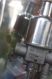
Burlen Ltd, the world’s only manufacturer of genuine SU (Skinner’s Union), AMAL and Zenith carburetors, is gearing up for an exciting 2017, with an innovative and truly ground-breaking product set to roll out of the workshop.

This game-changing launch from Burlen will be an all-new and complete fuelling system that includes a fuel injection device working inside an SU carburetor, and it’s set to completely shake up the market when it’s released in the summer.

Under the bonnet, it looks just like the world-famous SU carburetor that is known and loved around the globe, but hiding inside it is a complex and innovative fuel injection device that enhances performance and reduces emissions.

Four years in the making, the SUi system is the result of a simple idea and the determination to experiment and analyze the possibilities. Each SUi system comes complete with a new ECU, the required sensors, wiring and any other component that is required to fit the kit, all thoroughly tested and approved by the SU development team.

This innovative product is unlike anything else currently on the market. And as it’s an SU product that’s been put together with Burlen’s passion and professionalism, it comes with the ultimate seal of approval.

Launched initially for Jaguar XK/ E 4.2 six-cylinder engines, the SUi kit will be available for different engine sizes and states of tune. The next stages of development will see the kit suitable for a wider range of engines and applications.

This marks a new beginning for the SU brand and could well be a historic moment for the company that adds to its already rich heritage.

SU has an enviable history dating all the way back to 1900, when brothers George Herbert Skinner and Thomas Carlyle Skinner began experimenting with fuel mixture and atomization.

The S.U. Company Ltd was founded in 1910, and it’s been a carburetor superpower ever since. Over the generations, the keys to the Skinner’s Union castle were passed from Skinner to Skinner until Burlen acquired the name and rights of the company in 1996.

Burlen and Skinner’s Union first collaborated when John Burnett and Mike Cullen’s business was named as an official SU agent in the midst of the 1974 fuel crisis, but business wasn’t exactly booming.

Towards the end of the eighties, the SU brand was suffering from neglect as the factory was known as ARG Fuel Systems and fast-moving product was distributed by Unipart. However, Burlen came to the rescue and reached an agreement to relaunch the SU logo and livery as they appear today.

Despite SU being one of the oldest brands in the automotive world, Burlen’s youthful and exciting vision for the future has brought it into a completely new light.

Brothers Mark, Andy and Jamie Burnett are the masterminds and have worked at the company for over 15 years at all levels and now form the board of directors running the business. Their passion and excitement for the brand along with modern thinking and technical vision marks the start of a new era for Burlen.

Each brother has his own distinct personality and interests. Mark is a huge motorsport fan who even takes part in historic races himself, while Jamie is very passionate about classic and custom cars from across the Atlantic. Andy is a lover of historic military vehicles and weaponry.

It’s this real passion for cars that means the new board has complete empathy for classic car owners around the world and can draw on their own experience to bring game-changing products to market.

And their new direction for the company is epitomized by the upcoming product it will take to market, the first of several new developments to come in 2017.

More products will be launched over the course of the year, plus Burlen will make appearances at several high-profile events, including the Goodwood Revival.

Mark Burnett, Managing Director of Burlen, said:

The upcoming year is set to be an incredibly exciting one for Burlen. We’re always looking to the future and focusing on  both revolution and evolution, and our upcoming project is a welcome injection of fresh thinking in the classic car world. Of course, we strive to remember and stay true to our heritage, and we’re looking forward to showing off the best of the old and new world at events around the UK over the course of 2017.

Note: Press release courtesy Burlen Ltd