26 Oct

MIG versus TIG (grassrootsmotorsports.com)

MIG versus TIG
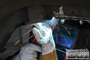
We’ve spent a lot of time discussing welding skills and technique in this magazine, but maybe it’s time to back up and start at the beginning: How do you decide what kind of welder to use in the first place?

Sure, the skills and techniques we’ve covered apply to all types of welding, but we’ve generally assumed that our readers are most familiar with MIG welding. The MIG approach has become nearly ubiquitous thanks to the availability of relatively inexpensive, high-quality machines from numerous manufacturers.

However, more and more members of the grassroots community are getting their hands on TIG welders. A new wave of lower-cost equipment and a bevy of craigslist ads hawking used machines have given enthusiasts another affordable way to weld.

If you sit around and bench race welders with your friends, one of them will quickly proclaim that TIG is better than MIG. Is that true? Well, let us put forth this proposition: As with most of life’s big questions, the answer is, “It depends.” The two types of welders operate differently, and each one has its advantages and disadvantages. We’ll let you make the final call based on your needs.

Hard or Soft?
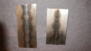
MIG and TIG welds feature different levels of hardness—technically called malleability. The piece on the left was TIG welded and hammered. The one the right was MIG welded and hammered, but cracked.

Let’s get right to it with some quick definitions. MIG stands for metal inert gas, while TIG stands for tungsten inert gas. Further, the M and T give us important information about each method’s heat source. Let’s dig into that subject next.

In the case of MIG welding, the heat source is the consumable wire. The wire and its arc heat the surrounding (base) metal, melting it together into a fused and welded joint.

With TIG welding, the heat source is the tungsten-tipped torch. The arc from the torch heats the surrounding metal, and then the consumable rod is melted in, forming the fused and welded joint.

Doesn’t sound like these two welders are all that different, right? Turns out they really are: Where the heat comes from and, more importantly, where the heat goes, can significantly affect weld quality.

With MIG welding, the heat starts at the weld joint and moves to the base metal. With TIG welding, the heat starts at the base metal and moves to the weld joint.

Another big factor is how the weld cools. A MIG weld cools much faster than a TIG weld. That’s because the base metal surrounding it serves as a heat sink that quickly sucks the heat from the MIG joint. A TIG joint, on the other hand, cools relatively slowly because the base metal is already very hot—and that means no heat sink effect.

A couple parts of this story will prompt the engineers to chime in with angry emails about our grassroots explanations of deeper science. Here’s their first opportunity to do so: Time to discuss the strength differences between these two types of welds.

Most people understand that heat treating metal usually involves heating it and then cooling it, often rapidly. When metal is heat treated, it often becomes harder, which implies—and means—more strength. This strength is often measured as tensile strength.

While high tensile strength is the real deal, it does have a couple side effects: increased brittleness and reduced malleability. Harder metal truly is stronger—but it’s only stronger until it breaks. Plus, sometimes brittleness is a bigger problem than low tensile strength.

Let’s apply this to how MIG and TIG weld joints cool. It turns out that a MIG weld joint becomes very hard and very brittle due to its fast cooling. Conversely, a TIG joint’s slower cooling leaves it softer and more malleable.

Clean or Dirty?
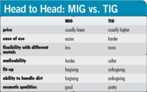
There’s more to these two types of welds than their strength and malleability. A large factor in the quality of a weld is the joint’s cleanliness, and this is another area where MIG and TIG welding are quite different.

Most people understand that the inert gas used in MIG and TIG welding plays a huge part in keeping the joint clean. However, they’re overlooking the role of heat.

Both machines circulate inert gas—usually argon, CO2 or a mix of both—around the weld joint to keep it from becoming contaminated with dirty ambient air. This process works very well, but the gas shouldn’t get all the credit. It turns out that heat can really help clean a weld joint, too, and that’s where MIG offers an advantage.

Think about a self-cleaning oven. It works by running at a very high temperature, burning the crud off the racks and interior surfaces. The heat concentrated at the MIG joint has a similar effect on the base metal, improving the quality of the weld.

You’ll remember that we strongly advocate cleaning weld joints thoroughly before welding. In fact, “You can’t weld dirt” is one of our welding mantras.

While buying a MIG welder won’t get you out of cleaning duties, sometimes it’s difficult to remove all of the grime. In these cases, MIG welding is your best bet. Maybe TIG isn’t always better than MIG after all. See how it depends?

Steel or Aluminum?
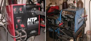
When it comes to home welding, many people gravitate toward MIG units (left). A TIG unit (right) doesn’t take up much more space in the shop, but the welding process is a bit more involved.

Now let’s go a little deeper into welding operation and theory. Engineers, here’s your second chance to scoff at our generalizations or grab your pitchforks.

We’ve talked about how heat affects the weld joint, and we’ve talked about where the heat is applied—at the joint or at the surrounding metal. It turns out that the polarity of the welder also affects where the heat ends up.

When welding steel, both MIG and TIG machines use DC current. There tends to be more heat on the positive side of an electrical circuit, and a MIG welder’s torch and wire typically handle that end of things; its ground wire is usually set to negative. This setup makes the MIG weld joint hotter and the base metal cooler.

A TIG welder’s polarity is the opposite. Its torch is set to negative and the ground is set to positive, which means heat travels into the base metal. Here’s the rule of thumb: With a MIG weld, two-thirds of the heat is in the weld joint and one-third is in the base metal. With a TIG weld, the inverse is true: Two-thirds of the heat is in the base metal and one-third is in the weld joint.

Let’s look at the TIG welding process a bit more. It uses DC current for steel, but it switches to AC current to tackle aluminum. Why the special treatment? Because aluminum is much more sensitive to contamination than steel. It’s also much more likely to crack.

Aluminum requires a welding process that can handle dirt well (like MIG) and create a less brittle weld joint (like TIG). TIG welding with AC current offers a set of compromises that make it more suitable for the job. Let’s dive even deeper into the process. An AC circuit reverses polarity 60 times per second on common household or industrial current sources. They don’t call it alternating current for nothing.

With TIG, the ideal setup for welding has the torch negatively charged and the base metal positively charged. The ideal setup for cleaning is when the polarity is reversed. Since AC current causes the polarity to switch constantly and rapidly, a single TIG welder can handle both the welding and cleaning processes. The result: a quality weld joint.

As a side note, more advanced TIG welders allow the user to adjust the AC process: You can lengthen the negative grounding wavelength to boost the cleaning capabilities, or lengthen the positive grounding wavelength for faster and more powerful welding.

So, what about welding aluminum with MIG? While it is becoming more common and practical to use specially equipped MIG welders for aluminum, TIG still tends to hold the advantage and is more flexible in most cases. This specific topic really warrants its own story, so keep your eyes peeled for that in a future GRM.

Simple or Complex?
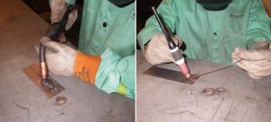
MIG (left) and TIG (right) machines both require the operator to use different techniques, but MIG welding is a bit easier.

If MIG welding is like throwing a ball, TIG welding is like juggling three of them. Guess which one is more difficult to master.

MIG welding can be a one-handed, point-and-shoot operation. You set the welder, pull the trigger, and off you go. With TIG welding, you’ve got to handle three different operations at once. One hand holds the torch and the other hand feeds the rod. Meanwhile, your foot is on the current pedal, and the harder you push, the more current (heat) you put into the weld.

As with juggling, these three factors must be in sync with one another or you’ll drop the ball and mess up the weld. So, this is another difference between MIG and TIG: It takes more time and practice to become proficient at TIG welding.

While that may make TIG seem less appealing, its complexity is actually a benefit. Good welding is about good control, and with a TIG welder you can dynamically control a lot more of the welding process.

With MIG, you set your current and wire speed before welding. After that, you don’t have to worry about them—but you can’t adjust them while you weld, either. TIG welding, on the other hand, allows you to make adjustments on the fly. If you need a little more heat, just press the pedal a little further. If you need a little less, back off a bit. More filler? Feed the rod faster. And so on.

TIG welders offer a level of flexibility that can greatly improve the quality of a weld. (Note: There are high-end MIG welders on the market that let you adjust these parameters as you go, but they’re generally out of reach for most enthusiasts.)

Another practical difference between these two welders involves prep work: MIG welding is more forgiving when it comes to the fit-up of the joint. Since TIG welding requires heating the base metal and then melting the rod, the base metal components need to fit together very tightly so they can be evenly heated and thus evenly melt the rod. If there’s an air gap, the weld will often fail. On the other hand, since a MIG welder’s heat source is the filler wire, it’s not only more forgiving to the base metal, but it can also fill air gaps to some extent.

Fast or Slow?

Whether you’re welding on the job or at home, time is usually money. MIG and TIG units operate at different paces, both before and during the welding process.

Assuming you have a higher-end MIG welder that can handle aluminum, converting it from its steel setting requires some work. Typically this means changing the shielding gas, the wire, the welder polarity (often with some disassembly of the welder) and even the liner or the whole welding torch assembly. Setting up a TIG welder for aluminum is usually as easy as flipping a switch from DC to AC and using a different rod.

However, MIG welding is typically a speedier operation than TIG welding. Since the wire feeds automatically and the heat gets in the weld joint faster, MIG welding is generally a timesaver.

We usually figure that MIG welding is about two to three times faster—that is, it will take two to three times as long to lay a 12-inch bead with TIG than MIG. That extra time may not matter to everyone, but especially in production environments, MIG can offer a distinct advantage.

See, It Really Does Depend

Finally, there’s the cosmetic factor. Even the staunchest defenders of metal inert gas will admit that TIG welds look better than MIG welds. Sure, MIG welds can look nice, but TIG welds can approach art. That stacked-coins look produced by a well-executed TIG weld is what most welders are after, especially on exposed welds.

Compared to the lumpier and less graceful look of the MIG weld, TIG work generally wins any beauty contest. So, is TIG better than MIG? It’s certainly got some advantages, but so does MIG. We hate to say it, but the answer really depends. At least now you have the information to make the decision for yourself.

Which is the best for us? How’s this for an answer: We’ve got both types in our shop, and we pick the best one for the operation at hand.

18 Apr

Make A Leak-Down Tester (www.mossmotors.com)

[A recent report of a Morgan owner performing a compression test on cylinders to determine performance state reminded me of a need to measure not only compression per cylinder but also leak down.  This tool is simple and cheap and this article talks you through the process.  Mark]

One of the simplest but most useful pieces of tune-up equipment is the cylinder-leakage tester. It can tell you if your engine has damaged valves, worn rings, a blown head gasket or a cracked block, thereby pinpointing compression leakage.

The cylinder-leakage, or leak-down, tester operates on a simple principle: A cylinder with its piston at top dead center (TDC) and both valves closed, should be reasonably airtight. By injecting a measured amount of air into each cylinder and observing the rate of leakage, you’re able to see if the cylinder-piston-valve assembly is good.

If the cylinder doesn’t hold the air, it has to be escaping – either past the rings, through one or both of the valves, through a crack in the head or block, or past a leaky head gasket. By simply listening at various points of possible escape, it’s relatively easy to determine exactly where the problem is. Worn rings will allow the air to seep into the crankcase and out the oil filler tube; a burned exhaust valve will allow air to exit through the exhaust system; a burned intake valve will allow air to exit through the carburetor; a cracked cylinder head or block will allow air to escape through the radiator, as will a defective head gasket, which also may let the escape from under the cylinder head.

Okay, that’s what a leak-down tester can do for you. If you’d like one, you can buy one from any of several reputable manufacturers for a few hundred dollars. Or you can make your own for about $35.

First, you need an air regulator. It must be fairly small and easy to handle, and it must be the self-relieving type. That is, capable of providing 0 to 100 psi without bleeding the line it’s connected to. You’ll need a regulator with two outlet ports, threaded for pipe thread.

The next item on your list is a 100 psi pressure gauge available from plumbing supply houses. Be sure to get one with a threaded fitting to mate with your regulator.

Next stop is you neighborhood auto-parts store for a length of high-pressure hose, an adapter to screw into your engine’s spark-plug holes and some air-line quick couplers to tie it all together. Either a length air-line hose 12 to 18 inches long or a high-pressure grease gun hose will work. Depending on the size of the hose’s threaded end you may need bushings. At any rate, it’s likely to be male thread, so buy an air chuck to fit it.

You’ll also need a second male air chuck to screw into the inlet port of the regulator, and a quick coupler with a 1/4 inch male threaded end. These items are available in most auto-supply stores or through large chain stores and should cost less than $5 total.

[Ok, maybe a few more than $5, taking into inflation into consideration. This article was written in 2007. Mark]

One of the male air chucks screws into the regulator’s inlet side. Use sealant on all threads to make sure the connections are air-tight. The pressure gauge screws into one outlet port and the female quick coupler goes in the other. Plug any other open ports in the regulator.

Screw the remaining air chuck onto one end of the hose and the spark-plug hole adapter on the other. Make sure you use the adapter that’s sized for your car’s spark plug holes; keep the other one in a safe place. There, you have a cylinder-leakage tester!

Now, the next step is to learn how to use it.

Start by removing all the spark plugs from your engine. (Make sure to mark all the wires first.) Next, you’ve got to bring piston No. 1 to TDC on the compression stroke – both valves closed. Screw the hose with the spark-plug adapter into the No. 1 cylinder’s spark-plug hole. Connect the other piece of your tester to the air supply by using the male chuck that’s screwed into the regulator. This charges the tester with pressure. Adjust the regulator until the gauge reads 100 psi. Now connect the two pieces of the tester together.

Since you’re no longer injecting air into the cylinder, your gauge reading will drop off as some air seeps past the rings.  A 20-percent drop in pressure is the generally accepted limit for a healthy cylinder. In other words, if it drops below 80 psi you’ve got a problem.  Before condemning your engine, however, be sure the test are done on an engine warmed to operating temperature. (A cold engine will not hold air as well as one that’s warmed up.) Also, be sure the piston is at TDC on the compression stroke. Remember – all cylinders leak, but at different rates. The less leakage, the better the cylinder.


19 Mar

How to Remove Scratches from Acrylic (Perspex) (www.plasweld.com.au)

This has got to be one of the most commonly asked questions – “can I get scratches out of Perspex?”

And the answer of course is, it depends!.

Light surface scratching can be buffed out of acrylic. Deep scratches on the other hand are a little more difficult but we will provide suggestions about address both.

Before we do though the first question to ask yourself has to be “is it worth it”? Is it worth spending time and money restoring something, particularly if it has a low replacement cost, or do you just bite the bullet and buy a new one.

If the scratches cover more than say 30% to 50% of the item or if the scratching affects a large area (half a square metre or more) it wouldn’t be worth the effort. If the acrylic is very old and has UV damage (signs of yellowing and/or crazing) it certainly will not be viable.

On the other hand, if it is a valuable item, a keepsake or something which is no longer available and it may be worth having a go. And of course these days many bathroom products like baths and hand basins are made from acrylic so these methods may be worthwhile trying in those situations.

So, first off light scratches:

• You will need some 800 and 1200 grit wet and dry paper, and some metal polish (Brasso works well).

• Fold the 800 grit and using water rub in a circular motion until most of the noticeable scratches become hard to see. Keep enough moisture on the paper so that a slight slurry forms.

• Move onto the 1200 grit and apply the same way with water until there is absolutely no sign of any scratches.

• Once satisfied that all scratches have been removed wipe dry with a clean soft cloth. The area that you have buffed may now seem duller that the surrounding acrylic so the metal polish (Brasso for example) can now be applied with a soft dry cloth to bring back the shine. It may take a few applications and a fair amount of rubbing. Work in a circular motion. Persistence and patience will pay off.

Deeper scratches:

• Deeper scratches can be buffed out the same way as above but you may need to start with 600 grit before moving on to 1200 grit and metal polish. If the scratch is particularly deep, say .5mm or more it probably isn’t worth it. A simple test is to run your finger over the scratch and if your nail really catches in the groove it may be too big to buff out.

01 Mar

Roadster Overheating Problem Solved

Hello All  :Some time back I posted a query about my Roadster overheating due to  fan not coming on. Thanks for all the helpful responses. Now that the problem has been fixed I thought I would relate my experience as it might be helpful should anyone else experience a similar problem. (Reminder:  I am a mechanical novice). So here is an update:

Bottom line is  that, through a process of elimination, I figured out that the rheostat that measures the air temp behind the radiator had failed.  Tried to find a replacement at several local auto parts stores without success.  (None even recognized what it was).

Then discovered that there is a very small part number (I am talking about getting out the magnifying glass)  under the coil on the back side, along with a similarly small Ford logo.  Took the part to the local Ford dealer who had never seen one before but checked their inventory and had one.  Walla!  Apparently it is quite an obscure part.

So, if you ever have  this problem here is the Ford  part number: F5RZ*8L603*AC, described as a “Resistor A”.  And be sure to  save the pigtail from the old switch as it will have to be soldered to the new one and then sealed.

Oh, one last thing.  After  installing, when I ws running the engine to test the switch I could not get it to turn on.  I stood there for 30minutes watching it  (watched pot etc.).  Finally figured out that because it was measuring air temp I  needed to close hood (oops;  bonnet)  to increase temp.  Closed hood and within  60 seconds it turned on.?

Again, thanks to everyone for all the feedback.  Next project, the oil pressure gauge.

John Stanley, Deland, Fl.

18 Dec

How to Wire Driving / Fog Lights (www.mossmotors.com)

Driving lights and fog lights came about as car owners navigated the twisting turning by-ways of misty England. Powerful lighting was necessary to illuminate the road ahead for potential hazards to be successfully identified and avoided. In addition, foggy and wet conditions caused by road spray obliterated the edges of poorly crowned roads. There is one more oft-omitted benefit to driving lights and fog lights, simply stated they are “racer cool”; installing these lights, however,on your favorite British sports car takes planning and preparation.

I remember the days when I rummaged about in my “box of wires” and grabbed any gauge wire of sufficient or insufficient length, splicing together a “rat’s nest” of wire connections and crimped ends to connect any number of desired accessories. After a few smoke-filled incidents I am much more careful.

Let’s begin with your lights already mounted to the car, the wires dangling beneath or behind and waiting to receive power from Mr. Lucas. The first order of business is to determine the amperage of your driving/fog lights. My lamps are vintage and each unit reads 35 watts. The formula for amperage is watts divided by volts equals amps, or W/V=A. Since I will be wiring the lights to the relay with one lead, 70W/12V= 5.8A. I will be using 14-gauge wire, which handles up to 11.8A. Amps are a measure of current flow; volts are a measure of the force behind the flow of current. To protect my 14-gauge wiring I will be installing 10-amp inline fuses. The rule of thumb is this: the fuse ought to be rated near 80% of the amperage of the wire. This will ensure that you blow the fuse before you burn the wire. In my case, 80% of 11.8A is 9.44A so a 10-amp inline fuse is perfect.

I will need several colors of 14-gauge wire: black, green, white, and red. The reason is simple, the color identifies the purpose of each wire and if I ever have a problem I can track it down using my wiring diagram. Here is what I need to complete the job:

  1. Two 10-amp inline fuses (as above)
  2. Wire in the gauge and colors described
  3. Relay (with four male spade connectors on back)
  4. Switch (with three male spade connectors on back)
  5. Female spade connectors (crimp style)
  6. Eyelet connectors (crimp style)
  7. Butt connectors (crimp style)
  8. Electrical tape
  9. Lock ties (small black type)
  10. Crimping tool and cutter for wire
  11. Electric drill and a 7/64” drill bit
  12. Sheet metal screws (for connecting ground wires to body)

A tidy wiring diagram is a must.

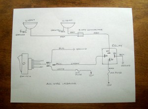
Before cutting any wire, a good diagram is in order. Draw a diagram on plain white paper with wire gauge noted and colors identified. Each component must be labeled. This wiring diagram will stay with the car so make it neat and easily readable. Pictured is my wiring diagram for installing two fog lights with fuses, a switch, and a relay. If you need assistance drawing a diagram, refer to your car’s factory workshop manual  [factory workshop manual??]. You’ll find examples of switches, lights, fuses—it’s helpful to understand and keep a universal language of the components in your drawings.

Relays are an important component in wiring fog or driving lights with a 30-60A draw. Basically, the relay protects the switch from getting hot and creating unwanted resistance. The low current through the switch triggers the relay to make a higher current connection to the heavy load of the fog lights. If you purchased your relay from a reputable source, it will have numbered terminals, which aid greatly in connecting everything correctly.

The fog lights are positioned first, the switch second, and the relay last. Since the switch will be on the dash and the fog lights at the front of the car, the only location decision to be made concerns the relay. I want the relay in a protected place near the front of the car. It needs to be near a 12V power source. I have chosen a position on the inner fender arch away from heat, but protected from road spray.

Use a test light to confirm your power sources for both the relay and the switch. I found a power source for my relay terminal number “30” on the low beam wire of the left headlight. I will splice into this wire so that my fog lights will work only when the low beams are on. I found a hot connection at the fuse block for the switch. Both of these 12V power lines need a 10-amp inline fuse.

Disconnect the battery!

Start with the ground connections for each component. Locate a suitable body connection point and drill a 7/64-inch hole in the body. Crimp an “eyelet” connector on the ground wire and screw a sheet metal screw through the “eyelet” and into the body. This must be done for the switch, the relay and each of the fog-lights. The relay ground terminal is numbered “85”.Now you are ready to run your wires according to the wiring diagram. Keep wires close to an existing wire loom and be careful of loops and sagging wires, which may snag on a moving component of the car. Do not add the crimped ends to any of the wires until all the wires are in place. Cut and leave about 6 inches of extra wire at every terminal point.

Drill the required hole in your dash for the switch; leave the switch free for the moment. I like to start wiring everything together at the switch and work my way toward the relay and the front of the car.

The switch has two remaining terminals. Connect a green wire from the “acc” terminal on the back of the switch to the number “86” terminal on the relay. The last terminal on the switch connects to the power source. This white wire will need a 10 amp inline fuse and is connected to the fuse block.

The relay is wired next. The power source for the relay is drawn from the low beam wire of the left headlight, as noted above. Splice a red wire from the headlight wire to the relay terminal “30.” This line needs a 10-amp inline fuse, so be sure and wire one in. The final terminal on the relay is numbered “87.” This terminal will carry power to the fog lights.

The fog lights each have two wires, one for ground and one for the 12V power. One of these wires from each fog light has already been connected to ground. A three-way connection must be made joining the second wire from each of the fog lights to the red wire going to the relay terminal “87.”

Finally, attach the switch to the dash and the relay to its location. A test is in order before you use the lock ties and button everything up.

Reconnect the battery

Turn on the ignition and hit your switch. Nothing should happen. Now, turn on your headlights to “low beam” and the fog lights will come on. Toggle the switch and see that the lights work properly. Use lock ties to secure all wires.

You are now ready to move about the country! Your lights will penetrate the fog and… they look “racer cool.”

By Ric Glomstad

06 Nov

How to Inspect Belts and Hoses for Overheating (www.consumerreports.org)

Check under the hood to spot problems before they become costly

A belt or hose failure can cause an overheated engine and loss of the electrical charging system. If a hose leaks coolant or the belt turning the water pump snaps, the cooling system is inoperable. If the engine overheats, it can suffer serious internal damage that requires expensive repairs and can ruin a summer vacation.

Overheating can occur anytime, but usually happens in the summer. Underhood temperatures are much higher, and heat can trigger or accelerate deterioration of rubber compounds.   

Coolant and heater hoses
Hoses are the cooling system’s weakest structural component. They are made of flexible rubber compounds to absorb vibrations between the engine and radiator, or, in the case of heater hoses, the engine and body’s firewall. Designed to hold coolant under high pressure, hoses are also subjected to fluctuating extremes of heat and cold, dirt, oils and sludge. Atmospheric ozone also attacks rubber compounds.

The most damaging cause of hose failure—electrochemical degradation (ECD)—isn’t easy to detect. According to engineers for the Gates Corporation, a parts maker, ECD attacks hoses from the inside, causing tiny cracks. Acids and contaminants in the coolant can then weaken the yarn material that reinforces the hose. Eventually, pinholes can develop or the weakened hose may rupture from heat, pressure, or constant flexing.

Some easy, basic maintenance can help prevent coolant hose failure:

  • Check the coolant-recovery tank often to ensure proper fluid level. Marks on the tank indicate the proper level for when the engine is cold or hot. If the tank is low after repeated fillings, suspect a leak. Also check for white, light green, or pink coolant tracks in the engine bay, which is residue left from leaking coolant.
  • When the engine is cool, squeeze the hoses with your thumb and forefinger near the clamps, where ECD most often occurs. Feel for soft or mushy spots. A good hose will have a firm yet pliant feel.
  • Inspect for cracks, nicks, bulges usually while hot), or a collapsed section in the hose and oil contamination, or fraying near the connection points.
  • Look for parallel cracks around bends (caused by ozone), a hardened glassy surface (heat damage), or abrasive damage (hose is rubbing).
  • Flush and replace the coolant according to the owner’s manual. Clean coolant is less likely to support ECD.
  • Never remove the radiator cap when the engine is hot. Also, be aware that an electric cooling fan can come on at any time.

The upper radiator hose fails more often than any other hose, followed by the water pump bypass hose (if your vehicle is so equipped), and the outlet heater hose from the engine to the heater core. Experts recommend, however, that all hoses be replaced at least every four years or when one fails. Always use replacement hoses designed to fight ECD. Trademarks will vary among hose manufacturers (Gates uses “ECR” for Electro-Chemical Resistant). Look for a “Type EC” label on the hose or its packaging. That is a Society of Automotive Engineers standard signifying “electrochemical.”

Accessory belts

Many of the same elements that attack hoses also attack belts—heat, oil, ozone, and abrasion. Almost all cars and trucks built today have a single multi-grooved serpentine belt that drives the alternator, water pump, power-steering pump, and air-conditioning compressor.   Older vehicles may have separate V-belts that drive the accessories. The Car Care Council says chances of a V-belt failure rise dramatically after four years or 36,000 miles, while the critical point for a serpentine belt is 50,000 miles. Any belt should be changed when it shows signs of excessive wear. But many new composite belts don’t show signs of wear until the failure occurs.

Here are tips for inspecting belts:

  • Look for cracks, fraying, or splits on the top cover.
  • Look for signs of glazing on the belt’s sides. Glazed or slick belts can slip, overheat or crack.
  • Twist a serpentine belt to look for separating layers, cracks, or missing chunks of the grooves on the underside.

Replacement belts should be identical in length, width, and number of grooves to the factory belt. Serpentine belts are usually kept tight with an automatic tensioner. Signs of a belt-tension problem include a high-pitched whine or chirping sound and vibration noises. Without proper tension, belts will slip and generate heat or fail to turn the accessories.

If in doubt, check with a qualified technician about any cooling problems, and always consult your owner’s manual for routine maintenance procedures.

04 Nov

Dashpot Oil (mossmotors.com)

Carb (SUs, Strombergs, etc.) Dashpots
Poor acceleration and “sputtering” during acceleration may be due to a low oil level in the carburetor dashpots. Automatic transmission fluid works well in some carbs, but not in others. The old recommendation of “the same oil as used in the engine” is a good place to start. If this gives too lean a mixture on acceleration, try a slightly heavier oil; if too rich, then a lighter oil is indicated. Fill to within 1/4 inch of the top of the hollow air piston rod. Do not overfill!

23 Oct

Good Fuel and Bad Fuel !!

Just back from the 2016 MOGSouth Fall Meet and GatorMOG Road Trip to Key West.  Wanted to post a tip about fuel that could affect any of you.

We had a unfortunate incident in Key West with bad fuel.   A Morgan was empty and a local gas station was spotted.

Several of the tanks were empty (low octane and one other, if I remember correctly) so the remaining (the only one still available) tank was chosen and used to fill a thirsty Morgan.

Once fueled, the Morgan got just a few yards beyond the gas station before it died and wouldn’t run any more.  The culprit was bad fuel.  Full of water.  We suspect, given that two of the tanks were empty, the third remaining one was on just the dregs and full of water.

Once we realized the problem, water in the fuel, we had to drain the entire tank and refuel with good gas.  All good after that.  The car ran strong for the rest of the trip.

The moral of this story is that if a gas station pump has a tank or two empty, the remaining one(s) might also be low and full of water.  Best to avoid them all together and find another gas station.

13 Oct

Tech 101 – How to use the right gasket sealants (blog.hemmings.com)

gaskets

With the varied composition of gaskets available on the market today, it is important that you use the proper sealant to ensure the gaskets seal effectively and not adversely affect the gaskets’ longevity.  In many cases, using the correct sealant will actually extend the life of the gasket because it offers protection from engine heat as well as resistance to corrosive chemicals found in oils, fuels and other fluids that can cause the gasket to deteriorate over time.

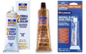
There are literally thousands of sealants available on today’s market, and we are not recommending one brand over another, but certainly Permatex is an industry leader, and many of the product characteristics for each type of sealant reflect equivalency to the Permatex standards, so we will use their standards as a guide.

A careful examination of what each category of sealants does and doesn’t do should point you in the right direction when deciding which type of sealant you should use.  Here are just a few of the basic groups of sealants enthusiasts should have on hand when tackling an engine, transmission, differential or minor repair.

Shellac – Often referred to as Indian Head after the Permatex product. Shellac is ideal for thin paper or cardboard gaskets that are mounted in a low temperature and/or low pressure environment.  It should not be used in temperatures higher than 300 to 350 degrees.  Resistant to engine fluids, its most common uses are in mounting thermostat, timing cover or differential cover gaskets. They are not resistant to many shop chemicals, thankfully, because they can be a real bear to clean off, if necessary in the future.

High Tack – Available in brush-top bottle or in tubes, High Tack is a non-drying gasket sealant that can be used in similar applications to shellac, but can sustain temperatures of up to 500 degrees. It remains tacky and also resists kerosene, propane and diesel fuels.

Form-a-gasket sealers – These are available in several types: fast drying, fast hardening (usually called #1); slow drying, non-hardening (usually called #2); brushable slow drying, non-hardening (usually referred to as aviation or #3). All three form-a-gasket sealers are rated to 400 degrees, but each serves a slightly different purpose.   Number 1 is most often used in applications you hope to never have to deal with again. It is often used to install block expansion plugs, threaded connections and to seal between metal-to-metal flanges.   Number 2 sealants work best on cork gaskets or paper oil pan gaskets.  Because they are non-hardening, clean-up is much easier when resealing is eventually needed. They are often used on neoprene transmission pan gaskets as well.  Aviation form-a-gasket has the advantage of being brushable, so you can lay on a thin or thick coat to seal metal flanges, machined surfaces and solid gaskets. It works well for sealing hose connections because it is fuel and oil-resistant.  It is also non-hardening for ease of resealing.

Copper gasket sealant – Available both in brushable and in aerosol forms, copper gasket sealer is fast-drying, and the metal content suspended within the sealant helps to dissipate heat and promote even heat transfer between the mating surfaces. It can also be used to fill small imperfections in the metal surfaces, promoting a more positive seal. Rated for up to 500 degrees, copper gasket sealant is best suited for cylinder head and exhaust manifold gaskets. It is also very easy to clean, even after extended periods of time.

Anaerobic sealers – Usually in a tube and red in color, anaerobic sealers are designed to be used in applications where outside air is not available to help the drying process. They were created to meet OE manufacturers’ requirements for a non-corrosive gasket maker in metal-to-metal applications. Anaerobic sealers are good for side-of-the-road leak repairs or for places where there never has been a gasket or the replacement gasket is no longer available. Anaerobic sealers will also fill small imperfections in mating surfaces.

RTV Silicone Sealers – Available in about a dozen different colors and spreadable via tubes, aerosol cheese-whiz-type cans or even in caulk-gun cartridges, Room Temperature Volatile silicone is effective as a gasket sealer as well as a gasket by itself. Temperature ratings and individual properties are available on a chart on the Permatex website. Basically, for applications up to 500 degrees, blue, black and grey are recommended. For up to 650 degrees, orange or red are recommended, and copper is good for temperatures up to 750 degrees. Whenever faced with a choice between a conventional RTV and an “Ultra” RTV, you should also consider that the Ultra products are sensor-safe for newer electronic-controlled vehicles.

Hylomar – This is a relatively new product in the aftermarket but has been used by many OE manufacturers for almost 30 years. It is a polyester urethane-based gasket compound that withstands temperatures of up to 500 degrees without hardening. It’s non-setting and remains tacky, making repeated disassembly and re-assembly much easier for racing applications where constant adjustments under the hood are necessary. It can be used as a gasket sealer or in place of a gasket. Hylomar could very well be the adjustable wrench of gasket sealers, fit for any do-it-yourself or professional tool box.